- 您现在的位置:买卖IC网 > Sheet目录17360 > MV036F240M005-CB (Vicor Corporation)VTM CURRENT MULTIPLIER EVAL BOAR
Not Recommended for New Designs / End of Life - Please see First Page
Electrical Specifications (continued)
MV036 SERIES
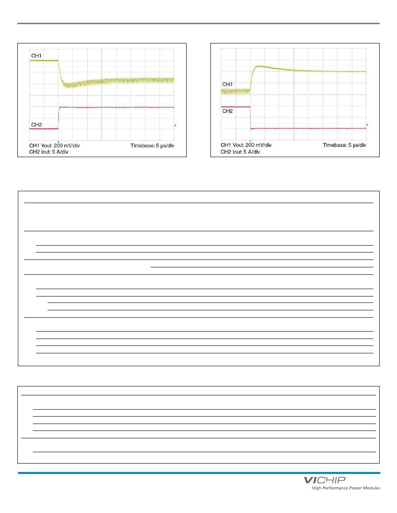
Figure 7 — Example load step with 100 μF input capacitance and no
output capacitance (MV036F120M010).
General
Figure 8 — Example load step with 100 μF input capacitance and no
output capacitance (MV036F120M010).
Parameter
Min
Typ
Max
Unit
Note
MTBF (MV036F030M040)
MIL-HDBK-217F
4,480,000
806,000
631,000
Hours
25°C, GB
50°C NS
65°C AIC
Isolation specifications
Voltage
Capacitance
Resistance
2,250
10
3000
Vdc
pF
M Ω
Input to Output
Input to Output
Input to Output
Agency approvals
Mechanical
cTüVus UL /CSA 60950-1, EN 60950-1
CE Marked for Low Voltage Directive and RoHS Recast Directive, as applicable
See Mechanical Drawings, Figures 10 & 11
Weight
Dimensions
Length
Width
Height
Thermal
0.53/ 15
1.28/ 32,5
0.87 / 22
0.265 / 6,73
oz /g
in / mm
in / mm
in / mm
Over temperature shutdown
125
130
135
°C
Junction temperature
Thermal capacity
Junction-to-case thermal impedance (R θ JC )
9.3
1.1
Ws / °C
°C / W
Junction-to-ambient
5.0
°C / W
With 0.25” heat sink?
Auxiliary Pins (Conditions are at 36 Vin, full load, and 25°C ambient unless otherwise specified)
Parameter
Min
Typ
Max
Unit
Note
Primary Control (PC)
DC voltage
Module disable voltage
4.8
2.4
5.0
2.5
5.2
Vdc
Vdc
Module enable voltage
2.5
2.6
Vdc
VC voltage must be applied when module is enabled using PC
Current limit
Disable delay time
2.4
2.5
6
2.9
mA
μs
Source only
PC low to Vout low
VTM ? Control (VC)
External boost voltage
External boost duration
12
14
10
19
Vdc
ms
Required for VTM start up without PRM
Maximum duration of VC pulse = 20 ms
MIL-COTS Chip Transformer
Page 5 of 10
Rev 2.9
01/2014
vicorpower.com
800 927.9474
发布紧急采购,3分钟左右您将得到回复。
相关PDF资料
BY251GP-E3/73
DIODE 3A 200V DO-201AD
EEV-HB0G470R
CAP ALUM 47UF 4V 20% SMD
RO-2405S/H
CONV DC/DC 1W 24VIN 05VOUT
MV036F180M007-CB
VTM CURRENT MULTIPLIER EVAL BOAR
MIC2545A-1BM TR
IC SW CURR LIMIT HI SIDE 8-SOP
SS10PH45HM3/86A
DIODE SCHOTTKY 10A 45V SMPC
A9BBA-0808F
FLEX CABLE - AFF08A/AF08/AFF08A
A9BAG-1603F
FLEX CABLE - AFF16G/AF16/AFE16T
相关代理商/技术参数
MV036F360M003
功能描述:MIL-COTS VTM CURRENT MULTIPLIER RoHS:是 类别:电源 - 板载 >> DC DC 转换器(分解式) 系列:V-I Chip™, VTM™ 应用说明:Factorized Power Architecture and V-I Chips 产品培训模块:VI Chip Bus Converter Modules 标准包装:1 系列:V-I Chip™, BCM™ 类型:总线转换器模块 输出数:1 电压 - 输入(最小):330V 电压 - 输入(最大):365V 输出电压:12.5V 电流 - 输出(最大):24A 电源(瓦) - 制造商系列:300W 电压 - 隔离:4.242kV(4242V) 应用:商用 特点:具有远程开/关功能和 UVLO 安装类型:通孔 封装/外壳:模块 尺寸/尺寸:1.28" L x 0.87" W x 0.26" H(32.5mm x 22.0mm x 6.7mm) 包装:托盘 工作温度:-55°C ~ 125°C 效率:95.3% 电源(瓦特)- 最大:300W 重量:0.031 磅(14.06g)
MV036F360M003-CB
功能描述:VTM CURRENT MULTIPLIER EVAL BOAR RoHS:是 类别:编程器,开发系统 >> 评估板 - DC/DC 与 AC/DC(离线)SMPS 系列:V-I Chip™, VTM™ 产品培训模块:Obsolescence Mitigation Program 标准包装:1 系列:True Shutdown™ 主要目的:DC/DC,步升 输出及类型:1,非隔离 功率 - 输出:- 输出电压:- 电流 - 输出:1A 输入电压:2.5 V ~ 5.5 V 稳压器拓扑结构:升压 频率 - 开关:3MHz 板类型:完全填充 已供物品:板 已用 IC / 零件:MAX8969
MV036T030M040
功能描述:MIL-COTS VTM CURRENT MULTIPLIER RoHS:是 类别:电源 - 板载 >> DC DC 转换器(分解式) 系列:V-I Chip™, VTM™ 应用说明:Factorized Power Architecture and V-I Chips 产品培训模块:VI Chip Bus Converter Modules 标准包装:1 系列:V-I Chip™, BCM™ 类型:总线转换器模块 输出数:1 电压 - 输入(最小):330V 电压 - 输入(最大):365V 输出电压:12.5V 电流 - 输出(最大):24A 电源(瓦) - 制造商系列:300W 电压 - 隔离:4.242kV(4242V) 应用:商用 特点:具有远程开/关功能和 UVLO 安装类型:通孔 封装/外壳:模块 尺寸/尺寸:1.28" L x 0.87" W x 0.26" H(32.5mm x 22.0mm x 6.7mm) 包装:托盘 工作温度:-55°C ~ 125°C 效率:95.3% 电源(瓦特)- 最大:300W 重量:0.031 磅(14.06g)
MV036T045M027
功能描述:MIL-COTS VTM CURRENT MULTIPLIER RoHS:是 类别:电源 - 板载 >> DC DC 转换器(分解式) 系列:V-I Chip™, VTM™ 应用说明:Factorized Power Architecture and V-I Chips 产品培训模块:VI Chip Bus Converter Modules 标准包装:1 系列:V-I Chip™, BCM™ 类型:总线转换器模块 输出数:1 电压 - 输入(最小):330V 电压 - 输入(最大):365V 输出电压:12.5V 电流 - 输出(最大):24A 电源(瓦) - 制造商系列:300W 电压 - 隔离:4.242kV(4242V) 应用:商用 特点:具有远程开/关功能和 UVLO 安装类型:通孔 封装/外壳:模块 尺寸/尺寸:1.28" L x 0.87" W x 0.26" H(32.5mm x 22.0mm x 6.7mm) 包装:托盘 工作温度:-55°C ~ 125°C 效率:95.3% 电源(瓦特)- 最大:300W 重量:0.031 磅(14.06g)
MV036T060M020
功能描述:MIL-COTS VTM CURRENT MULTIPLIER RoHS:是 类别:电源 - 板载 >> DC DC 转换器(分解式) 系列:V-I Chip™, VTM™ 应用说明:Factorized Power Architecture and V-I Chips 产品培训模块:VI Chip Bus Converter Modules 标准包装:1 系列:V-I Chip™, BCM™ 类型:总线转换器模块 输出数:1 电压 - 输入(最小):330V 电压 - 输入(最大):365V 输出电压:12.5V 电流 - 输出(最大):24A 电源(瓦) - 制造商系列:300W 电压 - 隔离:4.242kV(4242V) 应用:商用 特点:具有远程开/关功能和 UVLO 安装类型:通孔 封装/外壳:模块 尺寸/尺寸:1.28" L x 0.87" W x 0.26" H(32.5mm x 22.0mm x 6.7mm) 包装:托盘 工作温度:-55°C ~ 125°C 效率:95.3% 电源(瓦特)- 最大:300W 重量:0.031 磅(14.06g)
MV036T120M010
功能描述:MIL-COTS VTM CURRENT MULTIPLIER RoHS:是 类别:电源 - 板载 >> DC DC 转换器(分解式) 系列:V-I Chip™, VTM™ 应用说明:Factorized Power Architecture and V-I Chips 产品培训模块:VI Chip Bus Converter Modules 标准包装:1 系列:V-I Chip™, BCM™ 类型:总线转换器模块 输出数:1 电压 - 输入(最小):330V 电压 - 输入(最大):365V 输出电压:12.5V 电流 - 输出(最大):24A 电源(瓦) - 制造商系列:300W 电压 - 隔离:4.242kV(4242V) 应用:商用 特点:具有远程开/关功能和 UVLO 安装类型:通孔 封装/外壳:模块 尺寸/尺寸:1.28" L x 0.87" W x 0.26" H(32.5mm x 22.0mm x 6.7mm) 包装:托盘 工作温度:-55°C ~ 125°C 效率:95.3% 电源(瓦特)- 最大:300W 重量:0.031 磅(14.06g)
MV036T180M007
功能描述:MIL-COTS VTM CURRENT MULTIPLIER RoHS:是 类别:电源 - 板载 >> DC DC 转换器(分解式) 系列:V-I Chip™, VTM™ 应用说明:Factorized Power Architecture and V-I Chips 产品培训模块:VI Chip Bus Converter Modules 标准包装:1 系列:V-I Chip™, BCM™ 类型:总线转换器模块 输出数:1 电压 - 输入(最小):330V 电压 - 输入(最大):365V 输出电压:12.5V 电流 - 输出(最大):24A 电源(瓦) - 制造商系列:300W 电压 - 隔离:4.242kV(4242V) 应用:商用 特点:具有远程开/关功能和 UVLO 安装类型:通孔 封装/外壳:模块 尺寸/尺寸:1.28" L x 0.87" W x 0.26" H(32.5mm x 22.0mm x 6.7mm) 包装:托盘 工作温度:-55°C ~ 125°C 效率:95.3% 电源(瓦特)- 最大:300W 重量:0.031 磅(14.06g)
MV036T240M005
功能描述:MIL-COTS VTM CURRENT MULTIPLIER RoHS:是 类别:电源 - 板载 >> DC DC 转换器(分解式) 系列:V-I Chip™, VTM™ 应用说明:Factorized Power Architecture and V-I Chips 产品培训模块:VI Chip Bus Converter Modules 标准包装:1 系列:V-I Chip™, BCM™ 类型:总线转换器模块 输出数:1 电压 - 输入(最小):330V 电压 - 输入(最大):365V 输出电压:12.5V 电流 - 输出(最大):24A 电源(瓦) - 制造商系列:300W 电压 - 隔离:4.242kV(4242V) 应用:商用 特点:具有远程开/关功能和 UVLO 安装类型:通孔 封装/外壳:模块 尺寸/尺寸:1.28" L x 0.87" W x 0.26" H(32.5mm x 22.0mm x 6.7mm) 包装:托盘 工作温度:-55°C ~ 125°C 效率:95.3% 电源(瓦特)- 最大:300W 重量:0.031 磅(14.06g)
